
Residential lift diagrams serve as intricate blueprints, illuminating the inner workings of these essential vertical transportation systems. They offer a visual guide to the complex machinery that powers our ascension and descension within buildings. Let’s delve into the anatomy and functionality of these diagrams to unravel the mysteries behind our everyday rides.
When we step into a lift, we seldom ponder the engineering marvels that propel us effortlessly between floors. However, behind every smooth ride lies a labyrinth of gears, pulleys, and motors, meticulously choreographed to ensure our safety and comfort. At the heart of this intricate system lies the residential lift diagram, a blueprint that unveils the inner workings of these vertical conduits.
Anatomy of a Residential Lift Diagram
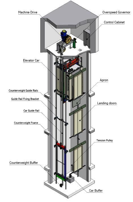
Residential lift diagrams are comprehensive illustrations that break down the components and mechanisms of an elevator system. From the elevator car to the control panel, every element is meticulously represented, providing engineers with valuable insights into the lift’s operation.
Deciphering the Internal Mechanism
Within the confines of a residential lift, a symphony of mechanical marvels orchestrates our vertical journeys. The diagram acts as a window into this world, revealing the interplay of pulleys, cables, and motors. Every line and symbol tells a story of efficiency and safety, ensuring our smooth passage from one floor to another.
The primary components depicted in these diagrams include the elevator car, counterweights, hoisting machinery, and control systems. Each element plays a crucial role in the lift’s operation, working in tandem to transport passengers with precision and reliability. By dissecting the diagram, engineers can identify potential areas of improvement and optimize the lift’s performance.
One of the key features illustrated in residential lift diagrams is the arrangement of pulleys and cables. These mechanisms form the backbone of the lift, responsible for hoisting the elevator car and counterweights. Through a system of traction or hydraulic drives, the motor exerts force on the cables, causing the elevator to ascend or descend gracefully. The diagram delineates the path of these cables, highlighting their strategic placement to minimize friction and maximize efficiency.
Exploring the Working of Pneumatic Elevators
Pneumatic elevators, a modern marvel in vertical transportation, operate on principles distinct from their traditional counterparts. Instead of relying on cables and counterweights, they harness the power of air to lift and lower their passengers. The residential lift diagram for such systems showcases the innovative use of pneumatic tubes and valves, illustrating how air pressure propels us skyward with remarkable efficiency.
In a pneumatic elevator, the diagram reveals the intricate network of tubes and chambers that comprise the lift shaft. When a passenger summons the elevator, a valve opens, allowing compressed air to rush into the tube beneath the elevator car. This sudden influx of air creates a cushion of pressure, lifting the car to the desired floor. To descend, the valve releases the air, and gravity gently lowers the car back to the ground level.
The beauty of pneumatic elevators lies in their simplicity and elegance. Without the need for complex cable systems or heavy machinery, these lifts offer a streamlined alternative for vertical transportation in residential settings. The residential lift diagram serves as a testament to human ingenuity, showcasing how innovative engineering can revolutionize the way we move within our built environments.
Maintenance and Safety Considerations
Beyond their role in understanding lift mechanics, residential lift diagrams also serve as vital tools for maintenance and safety protocols. Maintenance technicians rely on these diagrams to identify potential issues, troubleshoot problems, and perform routine inspections. By following the diagram’s guidance, they can ensure that the lift operates smoothly and safely for passengers.
Moreover, residential lift diagrams play a crucial role in establishing safety standards and protocols. Engineers use these diagrams to design and implement safety features such as emergency brakes, door interlocks, and overload sensors. By meticulously studying the diagram, they can anticipate potential hazards and implement preemptive measures to mitigate risks.
Accessibility and Inclusive Design
In recent years, there has been a growing emphasis on accessibility and inclusive design in the built environment. Residential lift diagrams play a pivotal role in this endeavor by facilitating the design of lifts that accommodate individuals with diverse mobility needs. Engineers use these diagrams to incorporate features such as wheelchair ramps, tactile buttons, and audible announcements, ensuring that lifts are accessible to all members of society.
By prioritizing accessibility in lift design, residential spaces become more inclusive and welcoming to people of all abilities. Whether it’s a senior citizen with mobility challenges or a parent with a stroller, everyone benefits from lifts that are designed with inclusivity in mind. Residential lift diagrams thus contribute to creating a more equitable built environment where everyone can navigate with dignity and independence.
Future Trends and Innovations
As technology continues to advance, the landscape of vertical transportation is evolving at a rapid pace. Residential lift diagrams offer a glimpse into the future of lift design, showcasing cutting-edge innovations and emerging trends. From sleek, space-saving designs to eco-friendly materials and energy-efficient systems, the possibilities are endless.
One notable trend is the integration of smart technology into residential lifts, enabling features such as remote monitoring, predictive maintenance, and personalized user experiences. With sensors and connectivity embedded into the lift system, engineers can gather real-time data on performance metrics, allowing for proactive maintenance and optimization.
Another promising area of innovation is the development of vertical transportation solutions for sustainable living. Residential lift diagrams play a crucial role in designing lifts that minimize environmental impact, such as regenerative braking systems, solar-powered elevators, and lightweight materials. By harnessing renewable energy sources and optimizing energy consumption, these lifts contribute to a more sustainable future.
Frequently Asked Questions (FAQs)
1. What is the purpose of a residential lift diagram?
Residential lift diagrams serve as detailed blueprints that illustrate the inner workings of lift systems. They provide engineers, technicians, and designers with valuable insights into the components, mechanisms, and operation of lifts, facilitating maintenance, troubleshooting, and design processes.
2. How do engineers use residential lift diagrams?
Engineers use residential lift diagrams for a variety of purposes, including:
- Identifying components and their functions
- Troubleshooting technical issues
- Planning maintenance schedules
- Designing new lift systems or upgrading existing ones
- Ensuring compliance with safety standards and regulations
3. What are some common components depicted in residential lift diagrams?
Some common components depicted in residential lift diagrams include:
- Elevator car
- Counterweights
- Hoisting machinery (motor, pulleys, cables)
- Control systems (buttons, sensors, safety features)
- Shaft and door mechanisms
4. How do pneumatic elevators differ from traditional elevators?
Pneumatic elevators operate on the principle of air pressure, using pneumatic tubes and valves to lift and lower the elevator car. Unlike traditional elevators that rely on cables and counterweights, pneumatic elevators offer a simpler and more space-efficient alternative for residential settings.
5. Are residential lift diagrams essential for safety?
Yes, residential lift diagrams play a crucial role in ensuring the safety of lift systems. Maintenance technicians rely on these diagrams to identify potential hazards, perform routine inspections, and implement safety protocols. Additionally, engineers use lift diagrams to design safety features such as emergency brakes, door interlocks, and overload sensors.
6. How do residential lift diagrams contribute to accessibility?
Residential lift diagrams facilitate the design of lifts that are accessible to individuals with diverse mobility needs. Engineers use these diagrams to incorporate features such as wheelchair ramps, tactile buttons, and audible announcements, ensuring that lifts are inclusive and welcoming to all members of society.
7. What are some future trends in lift design and technology?
Future trends in lift design and technology include the integration of smart features, such as remote monitoring and predictive maintenance, as well as the development of sustainable solutions, such as regenerative braking systems and solar-powered elevators. Additionally, advancements in materials and construction techniques are leading to more efficient and eco-friendly lift designs.
8. How can I ensure the longevity of my residential lift system?
Regular maintenance, informed by residential lift diagrams, is essential for ensuring the longevity and performance of a lift system. By following manufacturer recommendations and conducting routine inspections, homeowners can minimize wear and tear, address issues promptly, and extend the lifespan of their residential lift.